Do You Need Help? Here Us : Tel : +86 595 22486398
Do You Need Help? Here Us : Tel : +86 595 22486398

shock! New electric excavator adds two new functions
August 30, 2024
Excavators are one of the most important machines in the mining and construction industry. Today, fossil fuels provide most of the energy needed by excavators. Since this form of energy is harmful to the environment, the development of electric excavator functions is particularly important. Hydraulic excavators, in particular, consume a lot of energy even when not moving. Additionally, hoses and valves in hydraulic excavator systems waste energy, prompting researchers to apply electric linear actuators. These actuators are typically driven by an electric motor and a series of ball screws (or lead screws), which are required to withstand large axial stresses while dissipating energy when not in motion.
Extensive research explores the use of electric actuators in excavators. In the design and implementation of electric drive and control systems for mining excavators, a new mechatronic system for mining excavators is proposed that utilizes DC motors and transistor power sensors and aims to reduce power consumption by 20%~ 30%. Furthermore, in reducing the dynamic load on the excavator actuators, the researchers aimed to reduce the load on the excavator's electric actuators by incorporating an additional elastic damping device into the excavator's motion scheme.
The low backdrive capability of electric actuators prompted us to develop electric excavators with this feature. However, electric actuators typically produce less force than hydraulic actuators. Therefore, excavators using these actuators should be designed differently so that the actuators bear lighter loads with the same external loads on the bucket tip. This design can improve the load capacity of the electric excavator. At the same time, reducing the load on the actuator can reduce its energy consumption.
1. Design and manufacturing of electric excavators
This study proposes a novel design of an electric excavator utilizing a linear screw actuator, taking advantage of its lower reverse drive capability to save energy during idle periods and having a lower load capacity than a hydraulic actuator. Specifically, the parallel arrangement of the linear actuators in the new design is intended to reduce the load distribution across them (Figure 1).
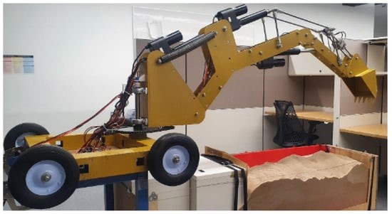
Figure 1. Fabricated excavator and test rig
The first three actuators installed on the excavator are electric linear actuators (Figure 2) for boom, boom and bucket movements, while the fourth actuator is a geared rotary DC motor for controlling swing movements. The rotating DC motor in an electric linear actuator is connected to the lead screw through a series of pulleys and belts. The motor is also connected to a rotary potentiometer, which provides feedback on the actuator length. Additionally, the linear actuators in this excavator are connected to the grid as a power source.
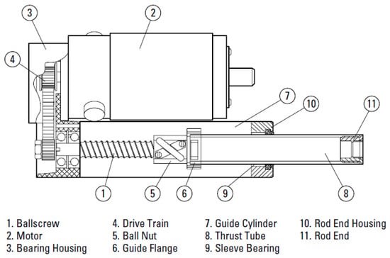
Figure 2. Components of a Linear Electric Actuator
The selected linear actuators have a dynamic load capacity of 2000 N and a moving speed of 20 mm/s. With the help of two huge tension springs, the boom link can be raised (Fig. 3). The maximum force of these springs is 70 kgf. The excavator’s structure is made from laser-cut 2D aluminum sheets and stainless steel. The excavator’s boom and boom are made of aluminum and assembled using M12 bolts.
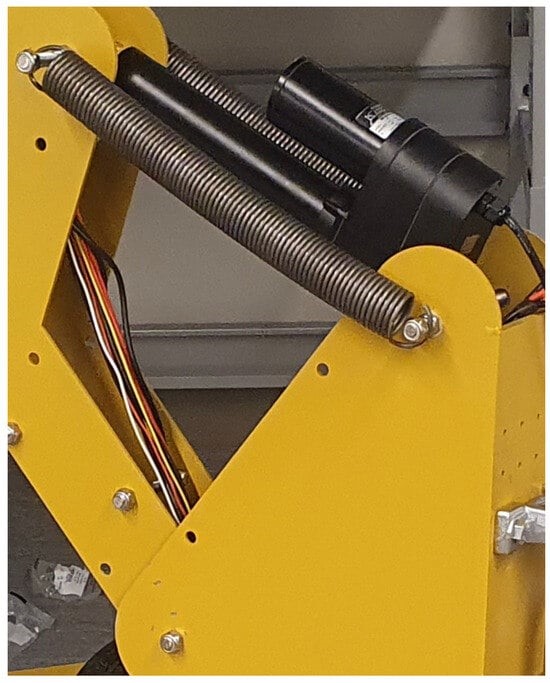
Figure 3 .Two huge springs help the boom actuator lift the robot hand
Four cut steel pipes are welded together with the steel plates below to form the bottom frame of the excavator (Figure 4). The structure has four inactive wheels to facilitate its movement. The excavator's manipulator (Figure 5) is then mounted to the bottom frame using two sturdy bearings.
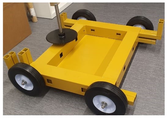
Figure 4 .Excavator substructure
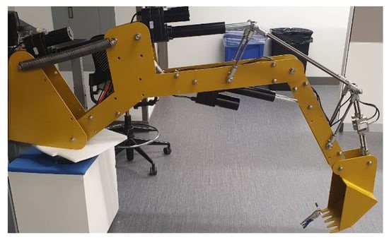
Figure 5 .The manipulator part of the excavator
For indoor testing, the excavator was positioned at a height of 85 cm and it was then driven to remove a pile of sand from the main container and transfer it to the side container. The main container features a clear acrylic panel that allows comparison of the actual path and excavated soil surface each time you dig. A depth camera, mounted at a distance from the transparent side of the main container and connected to the PC, monitors the sand profile in the container. Use MATLAB R2021a software to post-process the sensor data from the camera. The first step in post-processing is to capture and crop the data, then use the edge detection library in MATLAB to detect the contours of the sand in the container that are seen as ground shapes. In the final step, select the edge with the lowest height as the ground edge. The surface shape of the sand can be detected using this method, as shown in Figure 6. Sometimes, when sand adheres to a clear acrylic sheet, the edges need to be trimmed by hand.
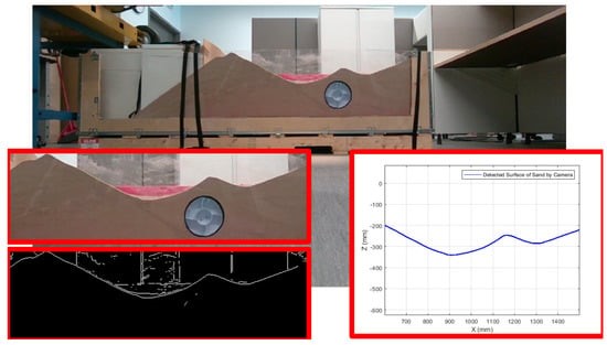
Figure 6. Use RGB camera and MATLAB R2021a software to detect ground shape
2. Path generation and tracking control methods
2.1. Path generation
In addition to using parallel actuators to save more energy by reducing actuator load, this study also considers optimal path generation to reduce the energy consumption of autonomous excavators. To this end, the excavator bucket is considered a mobile robot that can move in two dimensions and rotate around a single axis. These three DOFs (Degrees of Freedom) are controlled by boom, arm and bucket linear actuators.
Obstacles can be predetermined by the user or detected using any real-time detection method. Various methods are available for detecting the presence and location of underground objects. Among them, ground penetrating radar (GPR) and electrical resistivity tomography (ERT) have gained wide acceptance. However, these techniques are costly and time-consuming to implement and operate. Another study utilized cost-effective magnetic sensors fixed to the bucket of an excavator to detect and locate metal pipes and live wires based on magnetic fields. Like a mobile robot, the excavator bucket moves along a designated path while avoiding obstacles. But in order to create appropriate paths to reduce energy consumption, energy conservation is incorporated into further elements.
2.2 Path generation based on PSO
Particle swarm optimization (PSO) is a computational technique inspired by the collective behavior of animals such as birds and fish. It solves optimization problems by iteratively adjusting the position and velocity of particles in the search space. PSO aims to find optimal solutions by balancing exploration and exploitation.
This study utilizes the PSO algorithm to generate optimal paths aimed at minimizing energy consumption during excavation while avoiding underground obstacles. The main objectives are to reduce energy consumption, reduce the deviation of the excavation ground shape from the required contours and increase the distance to underground objects.
MATLAB simulation results show that the energy-saving PSO-based optimization process (Figure 7) can reduce energy consumption by 18.5% (Figure 8) compared to the same process without energy saving while trying to avoid underground obstacles and achieve closer The path of the desired ground shape.
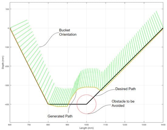
Figure 7 .Path generation simulation considering energy saving
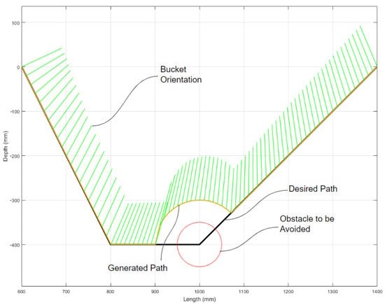
Figure 8 .Path generation simulation without considering energy saving
2.3 PFM-based path generation
In the PFM algorithm, the environment is represented as a potential field and the robot tries to reach the target with minimum potential energy. Therefore, in each iteration, the robot moves to adjacent positions with the smallest potential energy, and ultimately finds the best path to the goal by traversing these positions.
In PFM-based path planning, the robot tries to reach the target that pulls it. Experiments showed just the opposite: objects that the robot tried to move away from pushed it away. The magnitude of the thrust vector for the above objects may vary depending on the size of the object. Finally, the robot chooses its direction by adding these two vectors (the force vector caused by the target point and the object) and chooses its speed based on the magnitude of the summed vector.
To achieve energy-efficient movement, we built an artificial object that pulls the robot in a less energy-intensive direction. In this study, this artificial object is called the E object. However, this E object should be placed in an area where moving the robot towards it does not increase the distance between the robot and the target point (Figure 9). From several locations around the robot, the location that requires the least energy to reach will be selected as the E object.
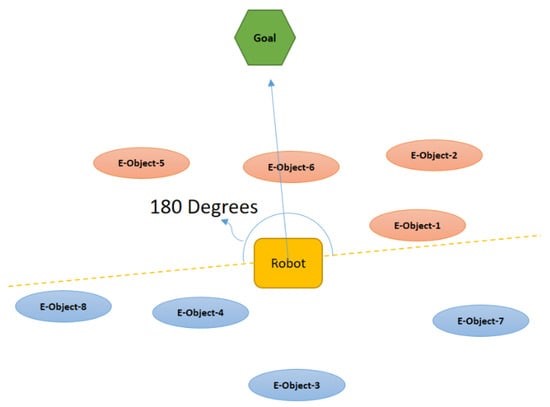
Figure 9. Candidate points for creating E-Objects that reduce energy consumption
Figure 9 illustrates how to select E objects that do not increase the distance between the robot and the target point. In order to reach these E objects (represented by orange ovals in Figure 9), the robot does not need to move far away from the target point. In Figure 9 and Figure 10, assume that E object 2 consumes the least energy among the orange candidates.
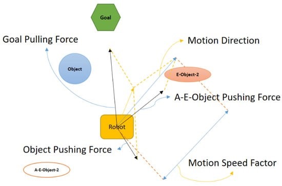
Figure 10. PFM with energy saving features
In order to adhere to the core idea of PFM that obstacles push the robot, an artificial energy object (AE-Object-2) was generated on the other side of the robot at the same distance (Fig. 10). The PFM algorithm will then determine the direction and magnitude of the robot's velocity, taking into account real and artificial energy obstacles as well as target points.
PFMs are generally less adaptable to dynamic conditions than PSOs. While PSOs can adapt to changing conditions through the exploration and exploitation capabilities of particle swarms, PFMs typically require static models to navigate effectively.
2.4 Path tracking control
Path following is equally important as path generation. This is because the generated path should be accurately tracked to achieve the desired motion, consuming the least amount of energy and minimizing the deviation between the tracked path and the created path.
This study proposes a new design for manufacturing an electric autonomous excavator that uses two parallel actuators to distribute the load and relieve the stress on each actuator. Electric excavators are designed to exert more force on the ground while consuming less energy. The proposed path generation method employing PSO and PFM algorithms was tested using a manufactured excavator. For this test, five different scenarios were examined and compared based on the type of trajectory generator, type of controller, and status of the energy-saving mode.
As future work, there are several possible approaches that could be applied to address the same topic. For example, a vector field histogram (VFH) can be used to determine possible navigation directions, avoiding obstacles and heading toward a goal based on a polar histogram of the environment created. As mentioned in the introduction, ACO (Ant Colony Optimization) may also be a valuable candidate. Furthermore, the developed algorithm was only tested in sand excavation in an indoor setting. This limitation stems from current excavator designs, which lack maneuverability and waterproofing. Therefore, drive wheels and waterproof covers must be incorporated into the excavator design for future deployment. This consideration will make it possible to conduct experiments in outdoor environments using a variety of materials such as silt, clay, and gravel. Additionally, this study used a camera positioned away from the transparent plate of the sandbox to monitor the ground contour, but this is impractical in an outdoor environment. Therefore, an additional sensor, such as lidar, is needed to handle this problem and accurately measure the ground shape.
Source: Department of Automotive and Mechatronics Engineering, Ontario Institute of Technology, Oshawa.

Please read on, stay posted, subscribe, and we welcome you to tell us what you think.
Add: Pudang Village, Xiamei Town, Nan'An City, Quanzhou, Fujian, China


Quanzhou Huamao Machinery Equipment Co.,Ltd All Rights Reserved.  Network SupportedSitemap | blog | Xml | Privacy Policy